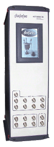


| Fast Z Feedback Loop | |
|---|---|
| Fast Input ADC | > 500 MHz Sampling rate, 16 Bit
resolution at 20 MHz band width single channel input - dc and amplitude detection possible |
| Fast DAC Output | Low noise, ultra-fast output DAC with more than 18 bit resolution (show details) |
| Digital Feedback Type | PI-Control with self-adjustment of the feedback
parameters 32 bit internal signal width, 40 MHz internal feedback loop |
| Dynamic Mode Specials | Anfatec provides a unique synchronous filtering
that offers an optimized high speed in dependence on the cantilevers resonance frequency. (show details for 1 MHz oscillation and 2 MHz oscillation) |
| Versatile | - every signal can be used as input signal - DAC output and input signals can be inverted independently |
| Feedback Modes | The software offers seven different feedback
types ranging from linear STM feedback over AFM contact and dynamic mode to PLL feedback |
| Scan Generator | |
|---|---|
| Scan Modes | standard scan mode with conventional overscan
(program generated) fast-scan mode with specialized output filtering (FPGA generated) |
| Fast Scan Mode | real-time, autonomous scan generator implemented
in an independent FPGA 2nd order low pass filtered outputs on the standard DAC's user-defined Line-Sync and Image-Sync offsets available (improves image linearity) maximum pixel rate: > 1 MHz system load checking -> safe operation |
| Standard Scan Mode | linear ramp output with parabolic overscan in
standard scan mode maximum pixel rate: 40 kHz |
| Low Voltage Signals | |
|---|---|
| Input / Output Range (all channels) | -10 V to 10 V / BNC connectors |
| Standard ADC/DAC | 8 channels ADC and 8 channels DAC 24 Bit resolution at 156 kHz sampling rate DAC-noise: 200 nV (show details), ADC-noise: < 0.3 mV |
Anfatec's controllers usually are designed for the customers special experimental set-up. The integrated High-Voltage Amplifier is a very useful option, because it allows us to adapt them to your piezo scanner in bandwidth, output voltage, and the amount of required channels. The numbers given in the table below are possible values out of whom the user should select what is required for his application.
| Channels | choose between three channels for stack scanners and five channels for tube scanners |
| Output Voltages | symmetric or unsymmetric to zero with up to ±
250 V e.g. -10 V to 150 V, -200 V to 200 V or differential output -70 V to 70 V |
| Technical Parameters | Bandwidth in Z: 1 MHz (show spectrum R(f))
or Phi(f))
Amplification and output noise depend on the type of HV amplifier. Typical output noise: < 500 nV/sqrt(Hz). (show spectrum) |
Similar to the HV amplifier, the coarse movement is a unique solution in each microscope. We offer various integrated solutions that enable automated tip approach and user defined sample or tip movement with a cordless joystick . Let's explain some of the options:
| Slip-Stick Movements | Define a ramp height and required rise and fall times for the fast and the slow ramp in connection with the capacitance to be driven - we'll design the electrical parameters with reference to your requirements |
| Stepper Motors | Up to three 2-phase stepper motors can be operated either in "Level-Station mode" or as X-Y-Z movement. Here, we adapt the drive current to your request. |
| DC Motors | We provide pulse width modulation outputs for dc motor operation. The set-up provided through our engineers includes that the moved distance is calibrated at your system. |
| Third party coarse move systems | Tables produced by other providers and operated through USB or serial connection (e.g. the Agilis station from Newport) can be implemented in the software so that they operate as if they were part of the system. |