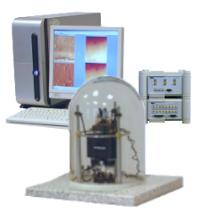
„Eddy“ is an Atomic Force Microscopy
system for student's education. It bases on the approved Level AFM
setup and includes a full sample set and a large cantilever set.
Some special features:
CCD camera
forward and backward tracing
auto save and auto approach functions
distance spectroscopy
oscilloscope
voltage spectroscopy
Among the prepared experiments are the standard measurements as
contact mode
Students learn the principle of the laser deflection system and how to
adjust the system.They can take an image in contact mode and check the
difference between slow feedback speed (constant height mode) and fast
feedback speed (constant force mode).
With distance curves, they can calculate the sensitivity of the system
and calculate the contact force used in the experiments.
Dynamic mode
For the daily use of AFM, the imaging in dynamic mode is more common
than the contact mode, because tip and sample are spared.The
students learn the relation between force constant and resonance
frequency, repeat some knowledge about harmonic oscillating systems,
resonances and Q-factors and get introduced to the basics of lockin
amplification technique, which is used to evaluate the amplitudes and
phase shifts.In the acquired images, material contrast can be obtained in the phase
image in addition to the topography.
Lateral force mode
In contact mode, lateral forces are detectable and can be used to find
material contrast in inhomogeneous samples.
The experiment explains how LFM is working and the students learn to
understand, how to distinguish between topography-related signals and
material-related signals.
but also some more enhanced experiments like
Force Spectroscopy
Kelvin Probe Force Microscopy
Kelvin Probe Force Microscopy
AM-KPFM image of an Al / silicon surface taken with a DEP01 cantilever with Pt coating.
Topography (left) and Surface Potentoal (right). The Al wire is buried into the silicon surface and
shows the more positive surface potential. The silicon is covered with a thin oxide laser and the surface
potential slightly decays in dependence on the distance from the Al edge.
Resonance enhanced FM-KPFM image of an Al / silicon surface taken with a DEP01 cantilever with Pt coating.
Topography (left) and Surface Potentoal (right). In comparison to the AM-KPFM image, the potential contrast
is better localized due to the side band detection. There are also more potential features visible on the Al
surface. The potential difference between Al and Si is measured with 190 mV.
Magnetic Force Microscopy(2nd trace imaging)
Magnetic Force Microscopy
Topography (left) and MFM Amplitude (right) images of a Bruker reference sample for MFM. Image Size: 1.5 �m x 1.5 �m.
Topography (left) and MFM Phase (right) images of a Bruker reference sample for MFM. Image size: 40 �m x 40 �m.
Electrical Force Microscopy
Electrical Force Microscopy
EFM Mode (Single trace)
Topography FWD
EFM Signal 1st Harmonic FWD
EFM Signal 2nd Harmonic FWD
EFM Mode (Dual trace = Lift Mode)
Topography FWD
2nd Trace Amplitude FWD
2nd Trace Phase FWD
All experiments are described step by step, that the student
can follow the instructions. The single instructions give a short introduction
in the theoretical knowledge and finish with a set of questions.
For more information click here:
Data Sheet
System parameters:
lateral resolution
better than 5 nm (at standard samples)
height resolution
better than 0,4 nm (atomic steps)
maximum scan range
30 m (standard, others possible on request)
maximum sample size
4 cm x 4 cm
manual positioning range
5 mm x 5 mm
accessories
130 cantilevers of different types, small empty
cantilever boxes, tweezers, sample holders, over 15 different samples
Microscope Description
The system consists of:
a base plate made from stone with wiring,
3 integrated miniaturized stepper motors for head levelling
standard AFM-head
laser diode maximum 3 mW, 670 nm with lens systemthree axis
high voltage amplifier V45C
DS4L-Modul with Interface to the AMU 2.4
Anfatec Measurement Interface AMU 2.4 (PCI bus board with integrated LockIn amplifier)
64-bit AMD processor
Accessories
Accessories
50 contact mode cantilever
Optional Features
Optional features for Anfatec AFMs
(not
necessary for standard applications)
EFM Module for AM-KPFM and FM-KPFM
Anfatec Present
Anfatec Present
- our software to evaluate your images -
filter functions (high pass, low pass,
Fourier, noise, mean,
..)
Besides its advantages for education, the Eddy Level AFM can
be used in the same laboratory for research purposes. There is no
limitation.


